
VFD-x20 Hardware Reference
DISCONTINUED: REFERENCE ONLY
This page describes the hardware, hookup, configuration and specifications of the VFD-420 and VFD-220 serial displays. For information on sending data and instructions to the display please see the programmer's reference.
Table of Contents
Cautions and Warranty
Handling, Usage and Operating Precautions
- Do not exceed the maximum supply voltage of 5.3Vdc.
- Always ensure that supply polarity is correct.
- If the screen requires cleaning, use low-tack tape to remove dust.
- Do not wipe or scrub the screen; it is easily scratched.
- In a permanent installation, mount the display behind a transparent window.
- Protect the unit from electrostatic discharge (ESD).
- Do not subject the display to sharp impact or mechanical pressure.
- Do not disassemble, drill or modify the unit in any way.
- Do not allow solvents, cleaners, or water to come into contact with the screen.
- Do not operate when wet or under conditions of condensing humidity (dew).
Seetron warrants this product against defects in materials and workmanship for a period of 90 days. If you discover a defect, we will, at our option, repair, replace, or refund the purchase price. Return the product with a description of the problem. We will return your product or its replacement via standard shipping. Expedited shipping is available at the customer's expense. Note: Violating the usage guidelines above, or attempting to repair or modify the module or the serial interface, voids this warranty.
Connection/Configuration
Hooking up a VFD-220 or -420 requires three connections: 5Vdc (regulated), serial input (2400 or 9600 bps, N81) and ground (connected to both power and the computer/controller).
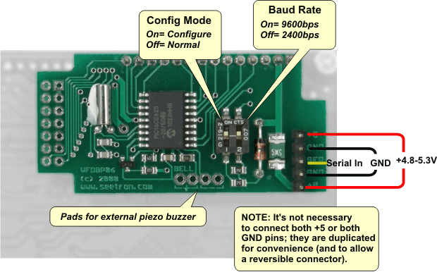
VFD-x20 Serial Interface Board.
Configuration Switches
There are two configuration switches on the serial interface. Always change switch settings with the power OFF; changes take effect next power ON. Functions:
- (1) Configuration Mode: OFF= Normal Operation, ON= Configure the display (software or ESC-W)
- (2) Serial Baud Rate: OFF= 2400bps, ON= 9600bps
Serial Input
VFD-x20 devices accept inverted serial input, such as the output of an *RS-232 port. The direct output of a UART is noninverted; it is not compatible unless inverted (NOT gate). In some cases, workarounds exist to avoid the additional component:
- Basic Stamp SEROUT instructions accept a parameter that inverts the output in software.
- Arduino v1.0+ SoftwareSerial supports inverted output:
SoftwareSerial(rxPin, txPin, 1);(where 1 sets inverted output). - PIC microcontrollers with the "enhanced" USART (EUSART) can be configured for inverted output by setting the SCKP bit of the BAUDCON register during USART initialization.
*RS-232 serial signals often use ±10V signals. These voltages will not harm the serial interface, which has a protective "clamp" circuit on its serial input.
Solder Pads
"Bell" Output. A piezo buzzer may be connected to the pads marked "BELL" on the interface board. The buzzer will beep when the ctrl-G Bell character is received. A compatible buzzer will have these specs:
- 5Vdc operation
- Internal oscillator (buzzer, not a speaker)
- Less than 25mA current draw
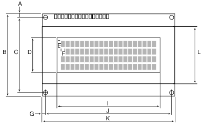
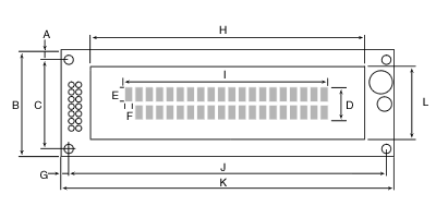
Dimensions (in mm)
Total depth (front of screen to highest point on pcb) is 30mm. Back and side-view drawings are TBD.
| VFD-420 | VFD-220 |
|---|---|
|
|
| Dim | Description | VFD-420 | VFD-220 |
|---|---|---|---|
| A | y offset edge to hole center (top & bottom) | 2.50 | 4.00 |
| B | y pcb height | 60.00 | 37.00 |
| C | y hole spacing | 55.00 | 29.00 |
| D | y screen opening | 25.20 | 11.50 |
| E | y character height | 4.75 | 4.70 |
| F | x character width | 2.95 | 2.40 |
| G | x offset pcb edge to hole center | 2.50 | 4.00 |
| H | x screen frame | 95.30 | 2.50 |
| I | x screen opening | 76.00 | 70.80 |
| J | x hole spacing | 93.00 | 108.00 |
| K | x pcb width | 98.00 | 116.00 |
| L | y frame height | 42.00 | 25.35 |
| - | mounting hole diameter | 2.50 | 4.00 |
| - | screen frame depth | 8.50 | 14.00 |
Mounting
An inexpensive mounting kit is available for VFD-420(PN: BEZ-420). There is no equivalent kit for VFD-220.
Specifications
| Power Requirements | 4.8 to 5.5Vdc at 300mA max |
|---|---|
| Serial Input (electrical) | RS-232 (±15V OK), inverted TTL |
| Serial Input (logic/data) | Inverted, 2400 or 9600bps |
| User Connector | 5-pin header, 0.025in. posts on 0.10in. centers |
| Connector Pinout | +5V Gnd Serial Gnd +5V |
| Operating Temp. | -0° to +70° C (-4° to 158°F) |
| Display Type | Noritake VFD |
| Character Size | 5x7 pixels, 4.70mm (0.18in.) height |
| Depth | 28mm (1.10in.) |